Schaefer C4500A SERIES AC/DC Power Supply
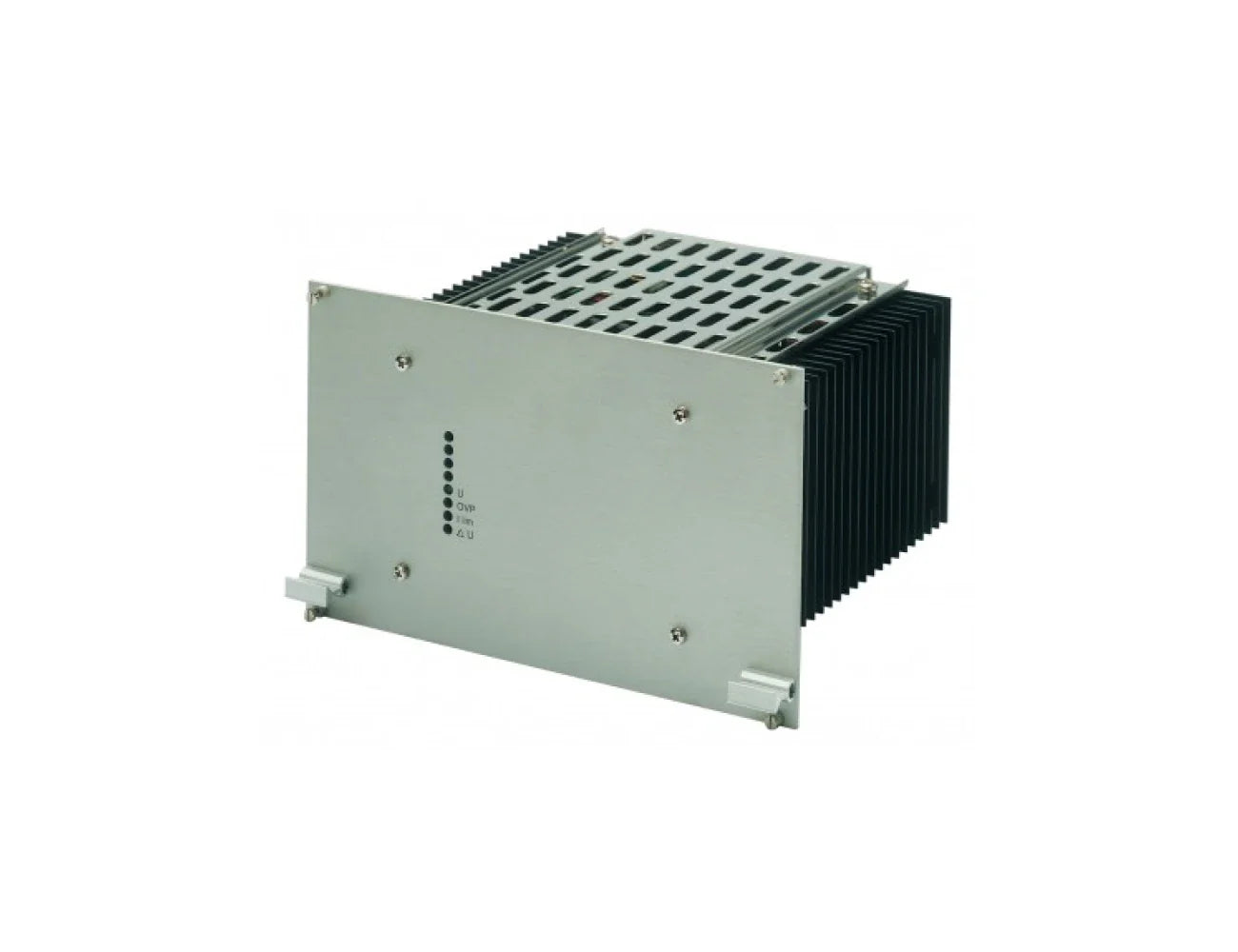
The Schaefer C4500A Series is a high-performance AC/DC power supply for industrial applications, delivering output power of 1600W. This series supports a wide range of DC output voltages from 9Vdc to 400Vdc. Designed for natural convection cooling, the C4500 Series ensures reliable performance in various environments. Mounting options include ch...
Read MoreThe Schaefer C4500A Series is a high-performance AC/DC power supply for industrial applications, delivering output power of 1600W. This series supports a wide range of DC output voltages from 9Vdc to 400Vdc. Designed for natural convection cooling, the C4500 Series ensures reliable performance in various environments. Mounting options include chassis mount, wall mount, or 19" rack installation when used with a separate 6U subrack. With options for monitoring, parallel/redundant operation, and conformal coating, the C4500 Series is ideal for demanding sectors such as Railway, Utilities, Mining, and Heavy Industry
Show Less
Features
- Industrial Grade AC/DC Power Supply
- Output Power: 1600W
- AC Input: 1-Phase and 3-Phase Models
- Wide Range of DC outputs: 9,12,15, 24, 28, 48, 60, 110, 220,400
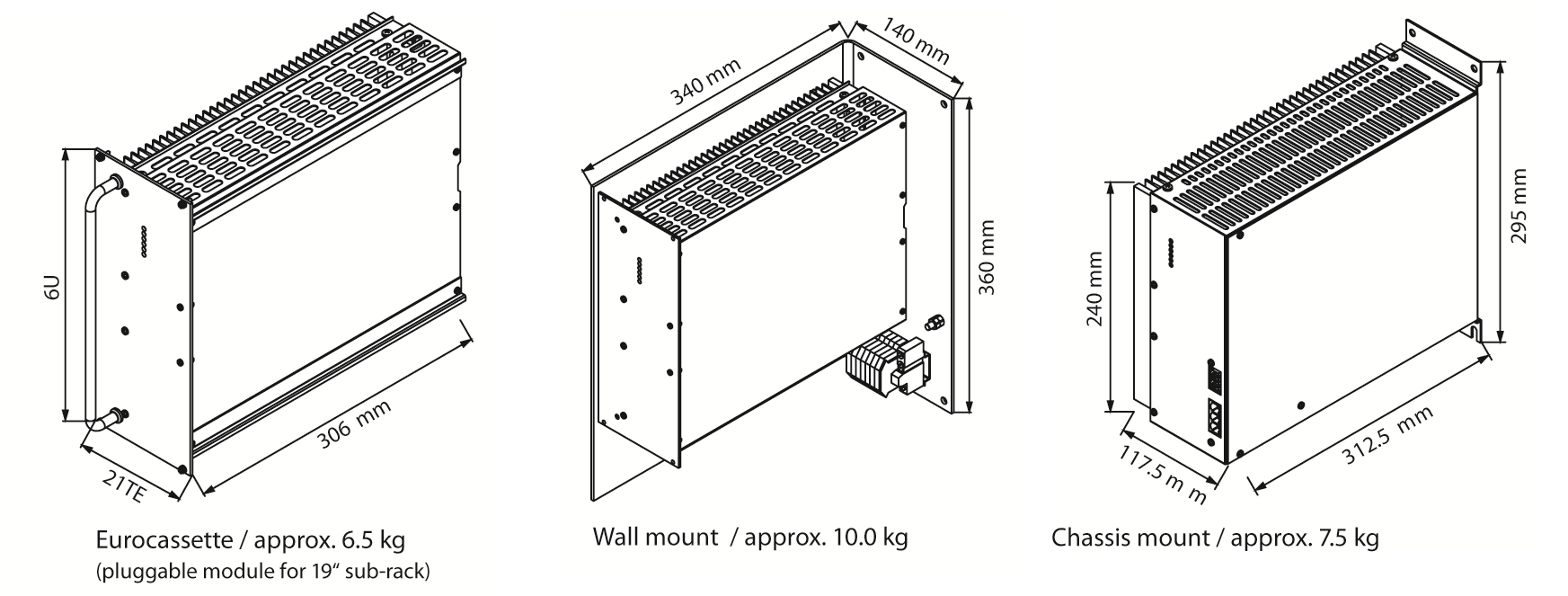
- Flexible mounting options via Chassis, Wall or Euro Cassette (19" rackmount via 6U subrack)
- Natural Convection Cooling (increased airflow via external fan recommended for high power applications)
Specifications
| INPUT | |
|---|---|
| Input voltage | 1ph 115/230Vac 3ph 200/400/480Vac See selection table Units will turn off with under or over input voltage. |
| No-load input power | 3-6W model (series dependant) |
| Inrush current | AC input limited by thermistor |
| Switch on time | 1-2 seconds. |
| Input Options | Option au: Autoranging for 115/230Vac input Option pr: Power OK via relay contacts |
| OUTPUT | |
|---|---|
| Output voltage | Voltage range; 4.5 - 400Vdc See selection table |
| Output current | See selection table. |
| Ripple & noise | 1% + 30mVpp |
| Line regulation | 0.1% (±10%) |
| Load regulation | 0.2% typical, load step 10-90% |
| Load transient | 6% typical, load step 10-90% |
| Response time | 2-3ms typical ±1% |
| Temperature coefficient | 0.02% per °C typical. |
| Holdup time | 10mS at 220VAC typical |
| Turn on rise time | 100mS typical (soft start) |
| Remote sensing | Standard for all series |
| Efficiency | 80%-92% typical |
| Output Options | Option dd: Decoupling Diode for redundant / parallel operation Option cs: Active Current Sharing Option h: Remote on/off (inhibit) Option dr: DC OK via relay contacts |
| PROTECTION | |
|---|---|
| Overload protection | Current limited at 105%–110% of full load. |
| Overvoltage protection | OVP switches off module with automatic return to operation |
| Protection Options | Option i: Inrush Current Limiting Option sd: Reverse polarity protection for DC input by Series Diode |
| MTBF | 100Khrs to 140Khrs at 40°C acc. to MIL-HDBK-217E (notice 1) |
| ENVIRONMENTAL | |
|---|---|
| Operating temperature | -20°C to +75°C (optional -40 to 75C) |
| Load derating | Derate 2.5% per °C, from +55°C to 75°C |
| Cooling | H: Heatsink - natural convection F: Fan - increased airflow recommended TF: Temperature controlled Fan included See selection table |
| Environment Options | Option c: Extended temperature range to -40°C |
| Storage temperature | -40°C to +85°C |
| Humidity | Up to 95% RH, non-condensing |
| STANDARDS | |
|---|---|
| EMI standards | acc. to EN61000-6-4 class A, optionally class B |
| Immunity standards | acc. to EN61000-6-2 |
| C-Tick | AS/NZS CISPR11: 2002 Group1 Class A |
| Safety / Construction | acc. to EN60950-1 / EN50178 |
| Protection category | IP20 acc. to EN60529 NEMA or others on request |
| MECHANICAL | |
|---|---|
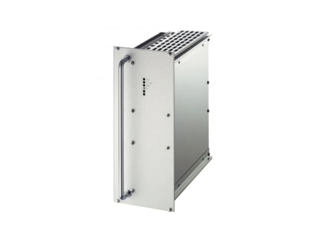
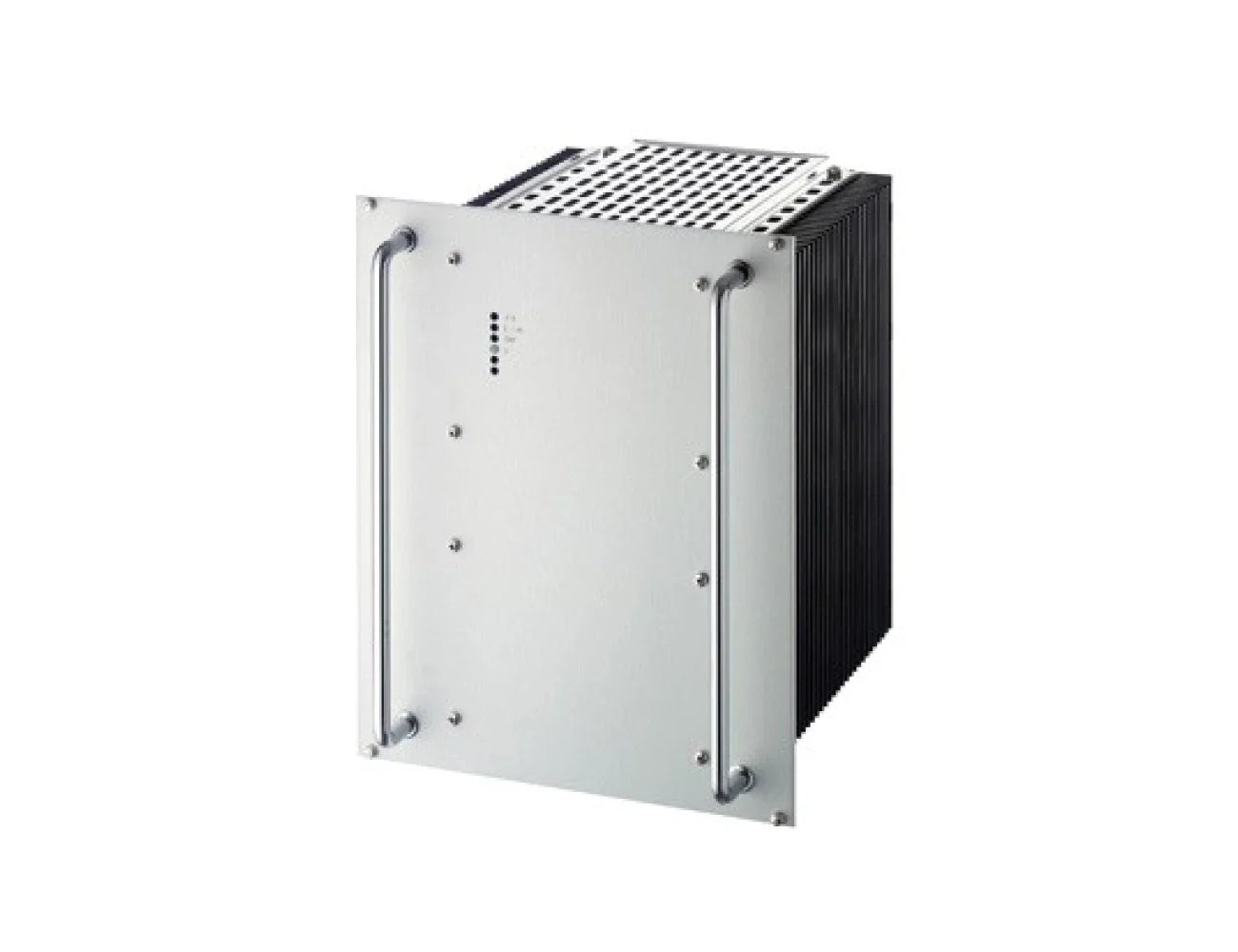
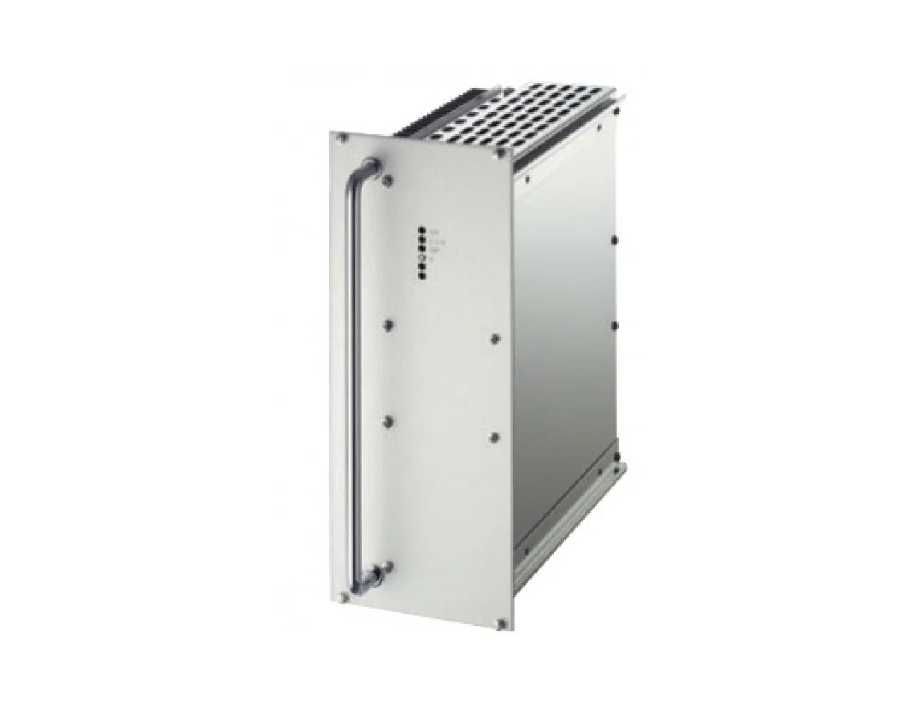
| Mounting | See technical illustrations Eurocassette, pluggable module for 19" subrack Option w: Wall Mounting Option cha: Chassis Mounting |
| Dimensions | See Technical illustration |
| Connector | H15 acc. to DIN 41612 H15 and high current connectors for I > 50A, or terminals / bolts / bars |
| Mechanical Options | Option ms: Increased Mechanical Strength Option t: Tropical protection |
| 19" Rack Mounting Options | Subrack Height 3U, 5U, 6U Wiring, Front Panels Accessories: Fuses, MCBs, Mains on/off switch Contact Powerbox for rack configuration |
Selection Table
| INPUT 115VAC ± 20% | INPUT 230VAC +15% - 20% | INPUT 115 ± 20% 230VAC +15% 20% | INPUT 3X200VAC +15%- 20% | INPUT 3X400VAC +15% - 20% | INPUT 3X480VAC +15% - 20% | OUTPUT AMPS | COOLING | OUTPUT VOLTAGE | VOLTAGE ADJUSTMENT |
|---|---|---|---|---|---|---|---|---|---|
| C4561 | C4581 | C4591 | C4561V | C4581V | C4591V | 110 | F | 9 | 8-10 |
| C4562 | C4582 | C4592 | C4562V | C4582V | C4592V | 96 | F | 12 | 11-13 |
| C4563 | C4583 | C4593 | C4563V | C4583V | C4593V | 80 | F | 15 | 14-16 |
| C4564 | C4584 | C4594 | C4564V | C4584V | C4594V | 56 | F | 24 | 23-26 |
| C4565 | C4585 | C4595 | C4565V | C4585V | C4595V | 50 | F | 28 | 26-30 |
| C4569 | C4589 | C4599 | C4569V | C4589V | C4599V | 30 | F | 48 | 45-55 |
| C4566 | C4586 | C4596 | C4566V | C4586V | C4596V | 24 | F | 60 | 58-68 |
| C4567 | C4587 | C4597 | C4567V | C4587V | C4597V | 13 | F | 110 | 100-130 |
| C4567J | C4587J | C4597J | C4567VJ | C4587VJ | C4597VJ | 8 | F | 200 | 190-200 |
| C4568 | C4588 | C4598 | C4568V | C4588V | C4598V | 6.5 | F | 220 | 200-250 |
| C4568J | C4588J | C4598J | C4568VJ | C4588VJ | C4598VJ | 4 | F | 400 | 380-400 |
| Cooling | H: Heatsink - natural convection F: Fan - increased airflow recommended TF: Temperature controlled Fan included See selection table |
||||||||
| Model configuration options: | Add the options to the model number, eg. C4594-dd-dr-cs Options for Input, Output, Environmental and Mechanical follow. |
||||||||
| 19" Rack Mounting Options | Subrack Height 3U, 5U, 6U Wiring, Front Panels Accessories: Fuses, MCBs, Mains on/off switch Contact Powerbox for rack configuration |
||||||||
| INPUT OPTIONS | |
|---|---|
| Option “i” | (inrush current limiting): A thermistor is connected in series with the input lines which changes its resistance from high to low when it gets hot. It does not reduce the current surge if the input power is interrupted for a short period of time not allowing the thermistor to cool down. Thermistors are fitted as standard to all mains input models except for 1-phase input of models > 2.5kW. Thermistors are available up to 45A. For higher input current an electronic inrush current limitation can be offered. |
| Option “ie” | electronic inrush current limiting An electronic circuit limits the inrush current. |
| Option “sd” | (series diode): A series diode protects the module against input voltage of wrong polarity (additional power losses). |
| Option “ad” | (anti-parallel diode): To avoid the power losses of a series diode a diode is provided with opposite polarity in parallel to the input blowing an internal or external fuse if the module is connected to a supply with wrong polarity. |
| Option “au” | (auto-ranging) For standard dual AC input models the range of 115/230Vac is to be selected by connecting the input line to different pins on the connector. With auto-ranging the unit senses the input voltage and provides automatically the correct connection. |
| Option “p” | (power fail): A signal (logic or relay) is given if the input voltage (AC or DC) drops below the specified limit. In AC input units we sense the rectified input voltage so that a power fail alarm will not be triggered if at light loads mains power returns before the input capacitors are substantially discharged. |
| Option “r” | (relay): A relay instead of a logic signal is provided for failure indication. |
| OUTPUT OPTIONS | |
|---|---|
| Option “dd” | (decoupling diode): For redundant operation the outputs of two or more units are paralleled behind de-coupling diodes so that an internal fault of one module does not affect the operation of the others. These diodes cause power losses. |
| Option “cs” | (active current sharing): An additional control circuit provides active current sharing via an interconnecting wire between converters that operate in parallel. Active current sharing should be used for multi-output units operating in parallel. |
| Option “csi” | (current sharing interrupt): Option "csi" will effect the removal of the "cs" signal. Should there be an instance where a unit is not supplying the load, then the effect of its "cs" signal is removed, and the load voltage is unaffected by this condition. |
| Option “h1” | (inhibit): A terminal connected to the negative input line also shuts off the converter. This can also be used in conjunction with a thermal trip which shuts the unit down. |
| Option “h2” | (inhibit): Operation of the unit is inhibited if a voltage signal (5V/10mA) is applied in reference to the negative line of the (main) output. |
| Option “rco” | (reducing current limiting at over temperature) A circuit reduces the current limiting level at higher temperature (to be specified). |
| Option “d” | (DC-ok, one output): A logic signal is given if the output voltage (main output in multi-output systems) is below the specified limit. |
| Option “m” | (DC-ok, all outputs): In multi-output systems a logic signal is provided if the voltage of any output is below the specified limit. |
| Option “ac” | (AC ok) A logic signal connected to relay contacts is given if the output voltage of an inverter is below the specified limit. |
| Option "y" | (sys-reset): This logic signal is a combination of power fail and DC-ok as specified for VME systems. |
| Option "r" | (relay): A relay instead of a logic signal is provided for failure indication. |
| ENVIRONMENTAL OPTIONS | |
|---|---|
| Option "t" | (tropical protection):The unit is given additional protection by a heavy coat of varnish on the printed circuit board(s) and components. |
| Option "c" | (extended temperature range):The circuit is designed and tested for operation at an ambient temperature as low as –40 °C. |
| Option "ms" | (increased mechanical strength): Screws are secured by Locktite and heavy components are fastened by ties and/or glue. Modules with the "ms" option meet the standard EN61373 regarding shock and vibration. |
| MECHANICAL OPTIONS | |
|---|---|
| Standard mounting | "Eurocassette" pluggable module for 19" sub-racks 8 |
| Option "w" | (wall mounting): Module is screwed against a mounting plate for installation in a cabinet. The load connections are typically a terminal block. |
| Option "cha" | (chassis mount) Module is designed for installation to a structure or within cabinet. Screw type connectors are supplied with the module. |
| Option "din" | (DIN rail mount) Module is designed for DIN rail mounting to a structure or within Cabinet. Screw type connectors are supplied with the module. |
Technical Drawings
Warranty & Returns
Warranty periods vary by product. Please refer to the Powerbox Warranty Policy for the applicable coverage period against manufacturing defects from date of purchase. For returns and RMA requests, please visit our RMA support page or contact our support team directly.
Related Products
- Industrial Grade AC/DC Power Supply
- Power Rating: 400W
- Available in wide range of DC output voltages (5 - 220Vdc)
- Chassis Mount, Wall Mount or 19" Mounting Options
- Input / Output isolation
- Overvoltage protection
- Thermal shutdown with auto-restart
- Op temp – 40 to +75 °C
- Industrial grade components
- High power density
- Compact robust design
- Convection cooled
- Industrial Grade AC/DC Power Supply
- Power Rating: 600W
- Available in wide range of DC output voltages (5 - 400Vdc)
- Chassis Mount, Wall Mount or 19" Mounting Options
- AC/DC Power Supply
- Industrial Grade
- High Operating Temp
- Hot Pluggable
- Configurable Options
- Eurocassette Mounting
- Wall Mounting
- Chassis Mounting
- Industrial Grade AC/DC Power Supply
- Power Rating: 400W
- Available in wide range of DC output voltages (5 - 220Vdc)
- Chassis Mount, Wall Mount or 19" Mounting Options
- 300 - 400W
- Industrial Grade
- AC/DC Power Supply
- High Operating Temp
- Hot pluggable
- Configurable Options
- Eurocassette Mounting
- Wall Mounting
- Chassis Mounting
- Industrial Grade AC/DC Power Supply
- Power Rating: 800W
- Available in wide range of DC output voltages (5 - 220Vdc)
- Chassis Mount, Wall Mount or 19" Mounting Options
- 650 - 800W
- Industrial Grade
- AC/DC Power Supply
- High Operating Temp
- Hot Pluggable
- Configurable Options
- Eurocassette Mounting
- Wall Mounting
- Chassis Mounting
- Industrial Grade AC/DC Power Supply
- Power Rating: 850W
- Available in wide range of DC output voltages (5 - 400Vdc)
- Chassis Mount, Wall Mount or 19" Mounting Options
- 700 - 850W
- AC/DC Power Supply
- Industrial Grade
- High Operating Temp
- Hot Plugable
- Many Configurable Options
- Subrack
- Wall Chassis and DIN Mounting
- Industrial Grade AC/DC Power Supply
- Power Rating: 1700W
- Available in wide range of DC output voltages (5 - 400Vdc)
- Wall Mount or 19" Mounting Options
- 1400 - 1700W
- AC/DC Power Supply
- Industrial Grade
- High Operating Temp
- Hot Pluggable
- Configurable Options
- Eurocassette Mounting
- Wall Mounting
- Chassis Mounting
- Industrial Grade AC/DC Power Supply
- Power Rating: 1250W
- Available in wide range of DC output voltages (5 - 400Vdc)
- Chassis Mount, Wall Mount or 19" Mounting Options

- Industrial Grade AC/DC Power Supply
- Power: 2.5kW
- Natural Convection Cooling
- Wall or Euro Cassette Mounting Options
- 2000 - 2500W
- AC/DC Power Supply
- Industrial Grade
- High Operating Temp
- Hot Plugable
- Configurable Options
- Eurocassette Mounting
- Wall Mounting
- Chassis Mounting

- Industrial Grade AC/DC Power Supply
- Power: 1.7kW - 2.5kW
- Natural Convection Cooling
- Wall, Chassis or Euro Cassette Mounting Options
- 1200 - 2500W
- AC/DC Power Supply
- Industrial Grade
- High Operating Temp
- Hot Plugable
- Configurable Options
- Eurocassette Mounting
- Wall Mounting
- Chassis Mounting

- Industrial Grade AC/DC Power Supply
- Power: 4kW - 5kW
- Fan Assisted Cooling
- Wall, Chassis or Euro Cassette Mounting Options
- 2400 - 5000W
- AC/DC Power Supply
- Industrial Grade
- High Operating Temp
- Hot Plugable
- Configurable Options
- Eurocassette Mounting
- Wall Mounting
- Chassis Mounting