
Delta Elektronika SM6K SERIES Bidirectional DC Power Supply
The Delta Elektronika SM6K Series is a 6kW bidirectional DC power supply that sources and sinks power from a single unit. Its regenerative design returns sink power to the grid, keeping heat dissipation low, and a constant-power output curve extends the usable range of voltage and current combinations. Four models cover outputs from 0–40Vdc at ±...
Read MoreThe Delta Elektronika SM6K Series is a 6kW bidirectional DC power supply that sources and sinks power from a single unit. Its regenerative design returns sink power to the grid, keeping heat dissipation low, and a constant-power output curve extends the usable range of voltage and current combinations. Four models cover outputs from 0–40Vdc at ±450A to 0–1000Vdc at ±18A.
The SM6K switches automatically between source and sink, and full-power two-quadrant operation keeps the DC output voltage constant whichever way power flows. High DC output isolation allows floating operation up to 1000V on every model, and the unit is rated for continuous full-power operation.
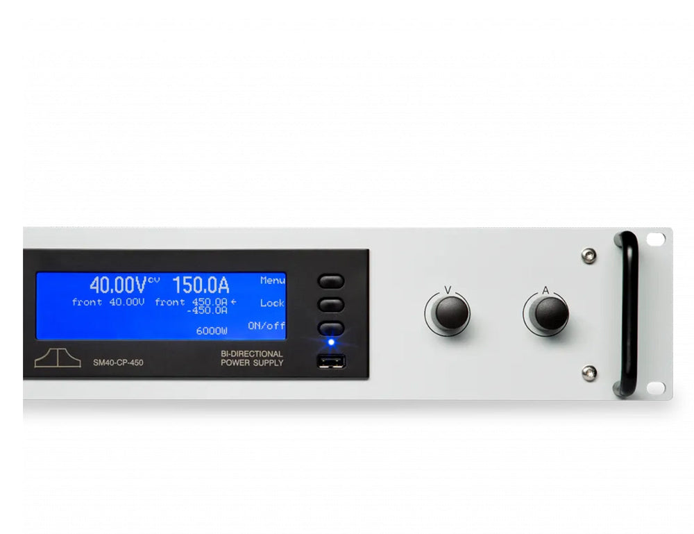
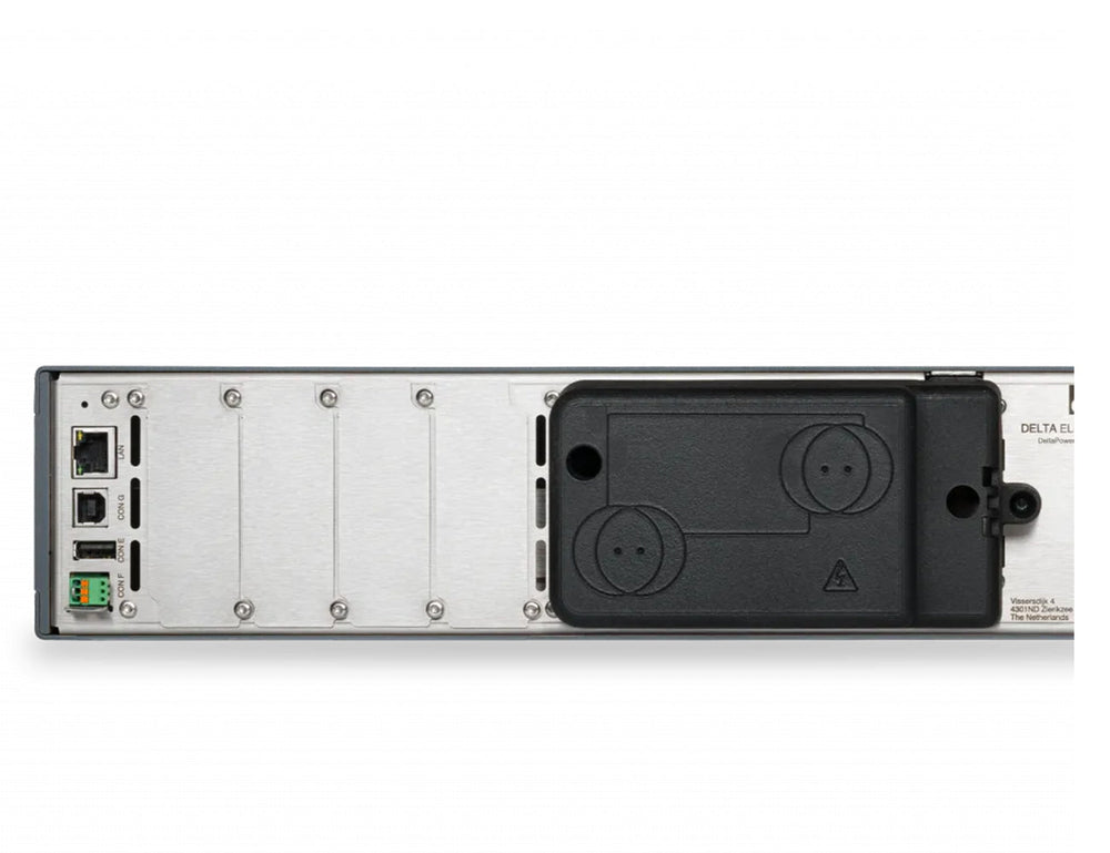
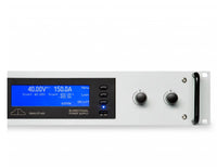
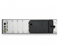
Built-in Ethernet supports SCPI programming and monitoring, with an integrated web interface for remote control. Long-life digital encoders with coarse/fine adjustment and full front-panel lock handle local setting. Four plug-and-play slots on the rear panel accept interface modules for isolated analogue programming, Anybus fieldbus (CANopen, EtherCAT, Ethernet/IP, Modbus-TCP, PROFIBUS, PROFINET), serial (RS232, RS485, RS422, USB), digital I/O, isolated contacts and Master/Slave operation. Delta Elektronika has scheduled interface module, sequencer and USB input functionality for a future firmware release.
Typical applications include PV simulation and inverter testing, automotive test systems and battery simulation, controlled battery charge and discharge testing, ATE in industrial production lines, precision current sources, PWM-controlled DC motor testing, renewable-energy systems, plasma chambers, lasers, and aerospace and defence applications.
For higher power, the Delta Elektronika SM15K Series bidirectional power supply applies the same source-and-sink approach at up to 15kW per unit.
Show Less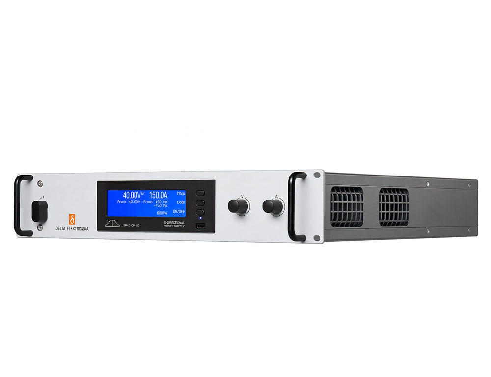
Features
- 6kW bidirectional DC source and sink with full-power two-quadrant operation
- Regenerative design returns sink power to the grid, keeping heat dissipation low
- Constant-power output curve extends the usable voltage and current range
- Automatic source/sink switching holds the DC output voltage constant
- Wide-range three-phase input (380–480Vac) suits 400Vac three-phase supplies
- Built-in Ethernet with SCPI and an integrated web interface for remote programming and monitoring
- High DC output isolation allows floating operation up to 1000V on all models
- Long-life digital encoders with coarse/fine adjustment and full front-panel lock
- Rated for continuous full-power operation
- Protected against overload and short circuit, with output shutdown at the 105% voltage self-protection level and on overtemperature
- Compact 2U, 19-inch rack-mount chassis, with stacking of units allowed
- Fast digital control with tunable load response
- Temperature-controlled fans keep audible noise to approx. 52dBA at full load and 25°C
- EMC performance beyond CE, with low emission and high immunity
- Four rear plug-and-play slots for analogue, fieldbus, serial, digital I/O, contact and Master/Slave modules (functionality planned for a future firmware release)
Specifications
| Output rating | ||||
|---|---|---|---|---|
| Parameter | SM40-CP-450 | SM75-CP-250 | SM330-CP-55 | SM1000-CP-18 |
| Voltage range | 0–40 Vdc | 0–75 Vdc | 0–330 Vdc | 0–1000 Vdc |
| Current range | -450–450 A | -250–250 A | -55–55 A | -18–18 A |
| CV = Constant Voltage; CC = Constant Current; CP = Constant Power. | ||||
| Specifications measured at Tamb = 25 ± 5 °C and Vin = 400 Vac, 3 phase, 50 Hz unless otherwise noted. | ||||
| TBD = To Be Determined. The information in this document is subject to change without notice. | ||||
| Regenerative mode | ||||
|---|---|---|---|---|
| Parameter | SM40-CP-450 | SM75-CP-250 | SM330-CP-55 | SM1000-CP-18 |
| Minimum sink voltage | 400 mV @ -450 A 125 mV @ -150 A 80 mV @ -45 A | 400 mV @ -250 A 130 mV @ -83.3 A 100 mV @ -25 A | tbd mV @ -55 A tbd mV @ -18.3 A tbd mV @ -5.5 A | tbd mV @ -18 A tbd mV @ -6 A tbd mV @ -1.8 A |
| Absolute maximum sink voltage | 42 Vdc | 78 Vdc | tbd Vdc | tbd Vdc |
| Minimum sink current | 0.4 % | 0.4 % | tbd % | tbd % |
| Source / sink transition | Unit switches automatically between source ↔ sink. | |||
| AC Input | ||||
|---|---|---|---|---|
| Parameter | SM40-CP-450 | SM75-CP-250 | SM330-CP-55 | SM1000-CP-18 |
| Rated voltage range | 380–480 Vac | |||
| Rated frequency | 50 / 60 Hz | |||
| Rated current | Maximum 12.2 A | |||
| Current, 6 kW | 9.8 A | |||
| Power factor, 6 kW / 3 kW | 0.995 / 0.988 | |||
| Internal fuses | 15 AT | |||
| Standby input power (Vo=Io=0)(1) | 160 W | |||
| Standby input power (Vo=Vmax)(1) | 185 W | |||
| (1) After 1 hour warm up | ||||
| Efficiency (Sink & Source mode) | ||||
|---|---|---|---|---|
| Parameter | SM40-CP-450 | SM75-CP-250 | SM330-CP-55 | SM1000-CP-18 |
| 6 kW, Iout=100 % | 92 % | 93 % | tbd | tbd |
| 6 kW, Uout=100 % | 95 % | 95 % | tbd | tbd |
| Regulation | ||||
|---|---|---|---|---|
| Parameter | SM40-CP-450 | SM75-CP-250 | SM330-CP-55 | SM1000-CP-18 |
| Load 0–100 %, CV(2) | 1 mV | 2 mV | tbd mV | tbd mV |
| Line 342–528 Vac, CV(2) | 1 mV | 1 mV | tbd mV | tbd mV |
| Load 0–100 %, CC(1,3) | 40 mA | 30 mA | tbd mA | tbd mA |
| Line 342–528 Vac, CC(1,3) | 1 mA | 4 mA | tbd mA | tbd mA |
| (1) After 1 hour warm up | ||||
| (2) Remote voltage sense | ||||
| (3) Local voltage sense | ||||
| Ripple + noise | ||||
|---|---|---|---|---|
| Parameter | SM40-CP-450 | SM75-CP-250 | SM330-CP-55 | SM1000-CP-18 |
| Source mode, measurement condition | 13.3 Vdc / 450 A | 24 Vdc / 250 A | 109 Vdc / 55 A | 333 Vdc / 18 A |
| Source mode, rms (BW = 300 kHz), CV(5) | 2.5 mV | 1.5 mV | tbd mV | tbd mV |
| Source mode, p-p (BW = 20 MHz), CV(5) | 15 mV | 12 mV | tbd mV | tbd mV |
| Source mode, rms (BW = 300 kHz), CC(5) | 35 mA | 20 mA | tbd mA | tbd mA |
| Source mode, measurement condition | 40 Vdc / 150 A | 75 Vdc / 80 A | 330 Vdc / 18.3 A | 1000 Vdc / 6 A |
| Source mode, rms (BW = 300 kHz), CV(5) | 4 mV | 1.5 mV | tbd mV | tbd mV |
| Source mode, p-p (BW = 20 MHz), CV(5) | 25 mV | 12 mV | tbd mV | tbd mV |
| Source mode, rms (BW = 300 kHz), CC(5) | 15 mA | 8 mA | tbd mA | tbd mA |
| Sink mode, measurement condition | 13.3 Vdc / 450 A | 24 Vdc / 250 A | 109 Vdc / 55 A | 333 Vdc / 18 A |
| Sink mode, rms (BW = 300 kHz), CV(5) | 1.6 mV | 1 mV | tbd mV | tbd mV |
| Sink mode, p-p (BW = 20 MHz), CV(5) | 15 mV | 10 mV | tbd mV | tbd mV |
| Sink mode, rms (BW = 300 kHz), CC(5) | 40 mA | 30 mA | tbd mA | tbd mA |
| Sink mode, measurement condition | 40 Vdc / 150 A | 75 Vdc / 80 A | 330 Vdc / 18.3 A | 1000 Vdc / 6 A |
| Sink mode, rms (BW = 300 kHz), CV(5) | 2.5 mV | 1.5 mV | tbd mV | tbd mV |
| Sink mode, p-p (BW = 20 MHz), CV(5) | 20 mV | 12 mV | tbd mV | tbd mV |
| Sink mode, rms (BW = 300 kHz), CC(5) | 25 mA | 15 mA | tbd mA | tbd mA |
| (5) Measured at full load | ||||
| Programming & monitoring accuracy | ||||
|---|---|---|---|---|
| Parameter | SM40-CP-450 | SM75-CP-250 | SM330-CP-55 | SM1000-CP-18 |
| Voltage(4) | ± 0.08 % | |||
| Current(4) | ± 0.15 % | |||
| (4) Excluding INT-MOD-ANA | ||||
| Temperature coefficient, per °C | ||||
|---|---|---|---|---|
| Parameter | SM40-CP-450 | SM75-CP-250 | SM330-CP-55 | SM1000-CP-18 |
| CV(1,5) | 15 ppm | 20 ppm | tbd | tbd |
| CC(1,5) | 40 ppm | 40 ppm | tbd | tbd |
| (1) After 1 hour warm up | ||||
| (5) Measured at full load | ||||
| Stability over 8 hours | ||||
|---|---|---|---|---|
| Parameter | SM40-CP-450 | SM75-CP-250 | SM330-CP-55 | SM1000-CP-18 |
| 25 ± 1 °C, CV(1,5) | 45 ppm | 35 ppm | tbd | tbd |
| 25 ± 1 °C, CC(1,3,5) | 40 ppm | 85 ppm | tbd | tbd |
| (1) After 1 hour warm up | ||||
| (3) Local voltage sense | ||||
| (5) Measured at full load | ||||
| Programming speed | ||||
|---|---|---|---|---|
| Parameter | SM40-CP-450 | SM75-CP-250 | SM330-CP-55 | SM1000-CP-18 |
| Rise time (10–90 %)(6,7), output voltage step | 0 → 13.3 Vdc | 0 → 24 Vdc | 0 → 109 Vdc | 0 → 333 Vdc |
| Rise time (10–90 %)(6,7), load = 6 kW | 0.6 ms | 1.5 ms | tbd ms | tbd ms |
| Rise time (10–90 %)(6,7), load = 600 W | 0.6 ms | 1.1 ms | tbd ms | tbd ms |
| Rise time (10–90 %)(6,7), output voltage step | 0 → 40 Vdc | 0 → 75 Vdc | 0 → 330 Vdc | 0 → 1000 Vdc |
| Rise time (10–90 %)(6,7), load = 6 kW | 2.8 ms | 4.6 ms | tbd ms | tbd ms |
| Rise time (10–90 %)(6,7), load = 600 W | 1.9 ms | 3.2 ms | tbd ms | tbd ms |
| Fall time (90–10 %)(6,7), output voltage step | 13.3 → 0 Vdc | 24 → 0 Vdc | 109 → 0 Vdc | 333 → 0 Vdc |
| Fall time (90–10 %)(6,7), load = 6 kW | 0.5 ms | 1.1 ms | tbd ms | tbd ms |
| Fall time (90–10 %)(6,7), load = 600 W | 0.5 ms | 1.1 ms | tbd ms | tbd ms |
| Fall time (90–10 %)(6,7), output voltage step | 40 → 0 Vdc | 75 → 0 Vdc | 330 → 0 Vdc | 1000 → 0 Vdc |
| Fall time (90–10 %)(6,7), load = 6 kW | 1.4 ms | 2.4 ms | tbd ms | tbd ms |
| Fall time (90–10 %)(6,7), load = 600 W | 1.8 ms | 3.0 ms | tbd ms | tbd ms |
| (6) Measured on resistive load with power supply in CV mode, different conditions may influence the specified speed. | ||||
| (7) Signal latency depends on the interface used & data traffic. | ||||
| Recovery time | ||||
|---|---|---|---|---|
| Parameter | SM40-CP-450 | SM75-CP-250 | SM330-CP-55 | SM1000-CP-18 |
| Condition(8,9) | 13.3 Vdc, 225 → 450 A | 24 Vdc, 125 → 250 A | 109 Vdc, 28 → 55 A | 333 Vdc, 9 → 18 A |
| Recovery within(8,9) | 100 mV | 100 mV | tbd mV | tbd Vdc |
| di/dt of load step(8,9) | 5 A/µs | 3 A/µs | tbd A/µs | tbd A/µs |
| Time(8,9) | 130 µs | 100 µs | 100 µs | 100 µs |
| Maximum deviation(8,9) | 0.6 Vdc | 0.4 Vdc | tbd Vdc | tbd Vdc |
| Condition(8,9) | 40 Vdc, 75 → 150 A | 75 Vdc, 40 → 80 A | 330 Vdc, 9 → 18 A | 1000 Vdc, 3 → 6 A |
| Recovery within(8,9) | 100 mV | 100 mV | tbd mV | tbd Vdc |
| di/dt of load step(8,9) | 2 A/µs | 0.9 A/µs | tbd A/µs | tbd A/µs |
| Time(8,9) | 75 µs | 100 µs | 150 µs | 150 µs |
| Maximum deviation(8,9) | 0.25 Vdc | 0.15 Vdc | tbd Vdc | tbd Vdc |
| (8) Local voltage sense. | ||||
| (9) Remote sensing and long wiring may influence the values. | ||||
| DC output capacitance | ||||
|---|---|---|---|---|
| Parameter | SM40-CP-450 | SM75-CP-250 | SM330-CP-55 | SM1000-CP-18 |
| X-capacitors(10) | 21 mF | 9 mF | tbd µF | tbd µF |
| Y-capacitors(10) | 860 nF | 860 nF | tbd nF | tbd nF |
| X-cap bleeder resistor(10) | 1.6 kΩ | 3.2 kΩ | tbd kΩ | tbd kΩ |
| Y-cap bleeder resistor(10) | 10 MΩ | 10 MΩ | tbd MΩ | tbd MΩ |
| (10) Typical | ||||
| Output impedance | ||||
|---|---|---|---|---|
| Parameter | SM40-CP-450 | SM75-CP-250 | SM330-CP-55 | SM1000-CP-18 |
| 0–1 kHz, CV(10) | < 1.5 mΩ | < 2 mΩ | < tbd mΩ | < tbd mΩ |
| 1–100 kHz, CV(10) | < 30 mΩ | < 40 mΩ | < tbd mΩ | < tbd mΩ |
| (10) Typical | ||||
| Pulsating load | ||||
|---|---|---|---|---|
| Parameter | SM40-CP-450 | SM75-CP-250 | SM330-CP-55 | SM1000-CP-18 |
| Max. tolerable AC component of load current, f > 1 kHz | 85 Arms | 60 Arms | tbd Arms | tbd Arms |
| Max. tolerable AC component of load current, f < 1 kHz | 450 Apk | 250 Apk | tbd Apk | tbd Apk |
| Hold-up time | ||||
|---|---|---|---|---|
| Parameter | SM40-CP-450 | SM75-CP-250 | SM330-CP-55 | SM1000-CP-18 |
| Vout = 100 %, Pout = 6 kW | 7.5 ms | 7.5 ms | tbd ms | tbd ms |
| Iout = 100 %, Pout = 6 kW | 7.5 ms | 7.5 ms | tbd ms | tbd ms |
| Vout = 100 %, Pout = 3 kW | 9.5 ms | 9.5 ms | tbd ms | tbd ms |
| Turn on delay | ||||
|---|---|---|---|---|
| Parameter | SM40-CP-450 | SM75-CP-250 | SM330-CP-55 | SM1000-CP-18 |
| Output power available(11) | 10 s after mains switch is turned on | |||
| (11) Unit should be configured to switch on the output at startup | ||||
| Inrush current | ||||
|---|---|---|---|---|
| Parameter | SM40-CP-450 | SM75-CP-250 | SM330-CP-55 | SM1000-CP-18 |
| Inrush current(10) | 30 A | |||
| (10) Typical | ||||
| Safety standards | ||||
|---|---|---|---|---|
| Parameter | SM40-CP-450 | SM75-CP-250 | SM330-CP-55 | SM1000-CP-18 |
| Safety standard | EN 61010-1 | |||
| Insulation | ||||
|---|---|---|---|---|
| Parameter | SM40-CP-450 | SM75-CP-250 | SM330-CP-55 | SM1000-CP-18 |
| AC / DC terminals | 3750 Vrms (1 min.) | |||
| Creepage / clearance | 8 mm | |||
| AC power terminals / case | 2500 Vrms | |||
| DC power terminals / case(12) | 1000 Vdc | |||
| (12) See "Safety Instructions" in the product manual. | ||||
| EMC | ||||
|---|---|---|---|---|
| Parameter | SM40-CP-450 | SM75-CP-250 | SM330-CP-55 | SM1000-CP-18 |
| Emission | EN 61326-1, class B equipment (for use in domestic establishments) | |||
| Immunity | EN 61326-1, equipment for use in industrial and domestic establishments | |||
| Environmental conditions | ||||
|---|---|---|---|---|
| Parameter | SM40-CP-450 | SM75-CP-250 | SM330-CP-55 | SM1000-CP-18 |
| Storage temperature | -40 to +70 °C | |||
| Operating temperature | -20 to +50 °C Derate output to 75 % at 60 °C | |||
| Overtemperature | Output automatically disabled at overtemperature | |||
| Humidity | Maximum 95 % RH, non-condensing, up to 40 °C Maximum 75 % RH, non-condensing, up to 50 °C | |||
| IP Rating | IP20 | |||
| Pollution degree | 2 | |||
| MTBF | ||||
|---|---|---|---|---|
| Parameter | SM40-CP-450 | SM75-CP-250 | SM330-CP-55 | SM1000-CP-18 |
| MTBF | 500,000 hrs | |||
| Series operation | ||||
|---|---|---|---|---|
| Parameter | SM40-CP-450 | SM75-CP-250 | SM330-CP-55 | SM1000-CP-18 |
| Master / slave operation | Series operation not allowed | |||
| Parallel operation | ||||
|---|---|---|---|---|
| Parameter | SM40-CP-450 | SM75-CP-250 | SM330-CP-55 | SM1000-CP-18 |
| Master / slave operation | tbd | |||
| Remote sensing | ||||
|---|---|---|---|---|
| Parameter | SM40-CP-450 | SM75-CP-250 | SM330-CP-55 | SM1000-CP-18 |
| Maximum voltage drop per load lead | Default 1 Vdc, can be set to 10 Vdc | |||
| Limits | ||||
|---|---|---|---|---|
| Parameter | SM40-CP-450 | SM75-CP-250 | SM330-CP-55 | SM1000-CP-18 |
| Adjustable voltage | 0–101 % | |||
| Adjustable current | 0–101 % | |||
| Adjustable power | 0–101 % | |||
| Fixed voltage overload level | 102.5 % - unit will continue to operate (OL-indication in display) | |||
| Fixed voltage self-protection level | 105 % - output is automatically disabled (PROT-indication in display) | |||
| Potentiometers | ||||
|---|---|---|---|---|
| Parameter | SM40-CP-450 | SM75-CP-250 | SM330-CP-55 | SM1000-CP-18 |
| Front panel control knob resolution | 15 bits | |||
| Meter scale | ||||
|---|---|---|---|---|
| Parameter | SM40-CP-450 | SM75-CP-250 | SM330-CP-55 | SM1000-CP-18 |
| Display | 4 digits | |||
| Voltage | 0.00–40.00 Vdc | 0.0–75.0 Vdc | 0.0–330.0 Vdc | 0–1000 Vdc |
| Current | -450.0–450.0 A | -250.0–250.0 A | -55.0–55.0 A | -18.00–18.00 A |
| Power | -6000–6000 W | |||
| Accuracy read output | 0.2 % + 2 digit | |||
| Mounting | ||||
|---|---|---|---|---|
| Parameter | SM40-CP-450 | SM75-CP-250 | SM330-CP-55 | SM1000-CP-18 |
| Mounting | Stacking of units allowed | |||
| AC terminals (CON A) | ||||
|---|---|---|---|---|
| Parameter | SM40-CP-450 | SM75-CP-250 | SM330-CP-55 | SM1000-CP-18 |
| Connection | Screw terminals for wire 4 mm², 3 phase + earth (no neutral) | |||
| DC terminals (CON B1 & B2) | ||||
|---|---|---|---|---|
| Parameter | SM40-CP-450 | SM75-CP-250 | SM330-CP-55 | SM1000-CP-18 |
| Connection | M12 bolts | M12 bolts | M8 bolts | M8 bolts |
| Programming connectors (LAN) | ||||
|---|---|---|---|---|
| Parameter | SM40-CP-450 | SM75-CP-250 | SM330-CP-55 | SM1000-CP-18 |
| Connection | Standard with RJ45-connector for Ethernet, 1000 Mb/s, full-duplex | |||
| Interlock (CON F) | ||||
|---|---|---|---|---|
| Parameter | SM40-CP-450 | SM75-CP-250 | SM330-CP-55 | SM1000-CP-18 |
| Interlock | Input for external floating contact | |||
| Cooling | ||||
|---|---|---|---|---|
| Parameter | SM40-CP-450 | SM75-CP-250 | SM330-CP-55 | SM1000-CP-18 |
| Cooling | Low noise, fan speed adapts to temperature of internal system | |||
| Audio noise level | ca. 52 dBA at full load, 25 °C ambient temperature, 1 m distance ca. 66 dBA at full load, 50 °C ambient temperature, 1 m distance | |||
| Airflow direction | From left to right | |||
| Thermal protection | Output shuts down in case of insufficient cooling (over temperature indication in display) | |||
| Dimensions | ||||
|---|---|---|---|---|
| Parameter | SM40-CP-450 | SM75-CP-250 | SM330-CP-55 | SM1000-CP-18 |
| Front panel: h x w | 88.1 x 483 mm (19", 2 U) | |||
| Behind front panel: h x w x d | 86 x 448 x 586 mm (excluding feet) | |||
| Optional interfaces | No additional depth is required with optional interfaces assembled | |||
| Weight | ||||
|---|---|---|---|---|
| Parameter | SM40-CP-450 | SM75-CP-250 | SM330-CP-55 | SM1000-CP-18 |
| Weight | 16 kg | |||
| Typical Applications | |
|---|---|
| PV | PV simulation and inverter testing |
| Automotive | Automotive test systems Automotive battery simulation |
| Battery testing | Controlled battery (dis)charge test |
| Industrial production | ATE in industrial production lines |
| Current sources | Precision current sources |
| DC motors | PWM-controlled DC motor testing |
| Energy | Renewable-energy systems |
| Other applications | Plasma chambers Lasers Aerospace applications Defence / military applications |
| Standard Features | |
|---|---|
| Bi-Directional Two-Quadrant Output | Full-power bidirectional two-quadrant operation keeps the DC output voltage constant whether power is sourced or sunk. |
| Digital CV- and CC- Settings | Long-life digital encoders on the front panel provide precise CV/CC setting with coarse/fine adjustment and full front-panel lock (including CV/CC knobs). |
| High Voltage Isolation | A high DC output isolation allows floating operation up to 1000 Vdc for all types. |
| Sequencer | Arbitrary Waveform generator or standalone automation. Sequencer functionality is planned for a future firmware release. |
| Ethernet Interface | Ethernet interface for programming and monitoring (SCPI), including an integrated web interface for remote control. |
| USB-Input | Front and rear USB inputs are intended for exchanging settings and waveform files. Sequences can be uploaded via the web interface. USB input functionality is planned for a future firmware release. |
| Interfaces | |
|---|---|
| Plug-and-play extension modules | Four slots are available at the rear of the power supply unit. See the Interfaces data sheet for details. Interface module functionality is planned for a future firmware release. |
| Isolated Analog programming (INT-MOD-ANA) | High speed and accurate analog programming and monitoring. |
| Anybus-carrier (INT-MOD-ANY) | Carrier for AnyBus CompactCom 40 fieldbus inserts: CANopen, EtherCAT, Ethernet/IP, Modbus-TCP, PROFIBUS, PROFINET. |
| Digital I/O (INT-MOD-DIG) | Interacts with sequencer and Ethernet programming. |
| Isolated contacts (INT-MOD-CON) | Programmable relays and floating interlock. |
| Serial communication (INT-MOD-SER) | RS232, RS485, RS422, USB. |
| Master/Slave (INT MOD M/S-2) | Series/parallel output functionality. |
Selection Table
| Model | Output Voltage (Vdc) | Output Current (A) | Output Power (W) |
|---|---|---|---|
| SM40-CP-450 | 0–40 | -450–450 | 6000 |
| SM75-CP-250 | 0–75 | -250–250 | 6000 |
| SM330-CP-55 | 0–330 | -55–55 | 6000 |
| SM1000-CP-18 | 0–1000 | -18–18 | 6000 |
Warranty & Returns
Warranty periods vary by product. Please refer to the Powerbox Warranty Policy for the applicable coverage period against manufacturing defects from date of purchase. For returns and RMA requests, please visit our RMA support page or contact our support team directly.
FAQs
Related Products

- Bi-directional power supply with standard 15 kW source and sink
- Easy Master/Slave parallel operation up to 60 units
- Designed for long life at full power

- 300W Laboratory Supply
- 0 - 30Vdc and 0 - 10A
- Very Low Output Ripple
- V & I control 10 turn pots
- Excellent Dynamic Response
- High programming speed

- 800W Laboratory
- 0 - 7.5V to 0 - 400V
- 0 - 4A to 0- 80A
- Low Output Ripple
- Stable Output Voltage
- Stable Current
- Programming Option

- 1500W Laboratory
- 0 - 15V to 0 - 400V
- 0 - 6A to 0 - 100A
- Low Output Ripple
- Stable Output Voltage
- Stable Current
- Programming
- Master/Slave

- 3300W Laboratory
- 0 -18V to 0 - 660V
- 0 - 11A to 0 - 220A
- Auto Ranging output Low Output Ripple
- Software control
- Long Life