Delta Electronics FORCE GT 960W 3-Phase Series AC/DC Power Supply
The Delta Force GT 960W 3-Phase DIN rail power supplies are engineered for heavy-duty industrial applications demanding maximum power density, exceptional efficiency, and stable performance under extreme electrical and environmental conditions. Positioned alongside top-tier global brands such as Phoenix Contact, Weidmüller, TDK-Lambda, and PULS,...
Read MoreThe Delta Force GT 960W 3-Phase DIN rail power supplies are engineered for heavy-duty industrial applications demanding maximum power density, exceptional efficiency, and stable performance under extreme electrical and environmental conditions. Positioned alongside top-tier global brands such as Phoenix Contact, Weidmüller, TDK-Lambda, and PULS, the Force-GT Series offers a premium, future-proof power solution for modern automation and control systems.
Designed for high-power 24 Vdc and 48 Vdc systems, the 960W models support both 3-phase and 2-phase universal AC input (320–575 Vac and 340–575 Vac respectively), with no derating required across the full 3-phase voltage range. Surge immunity is elevated to an industry-leading 6 kV when used with SPD protection, while advanced EMC performance meets heavy industrial Class B emission and EN/IEC immunity standards.
A built-in constant current circuit enables reliable operation for inductive loads and battery-charging applications. Long-life electrolytic capacitors, conformal-coated PCBAs, and natural convection cooling ensure stable operation in harsh environments, with cold-start capability down to –40°C and full-load operation up to +70°C (3-phase).
Integrated DC OK relay contacts and a green LED indicator provide straightforward diagnostic monitoring, and the ultra-slim 110 mm housing width optimises valuable DIN rail space in compact control cabinets.
With global safety approvals, low no-load power consumption, and rugged mechanical design, the Force-GT 960W Series delivers a robust, high-quality, and cost-effective alternative to established European and Japanese power supply brands — giving system integrators a dependable, high-efficiency choice for industrial automation, robotics, machine control, conveyors, and distributed power architectures.
Show Less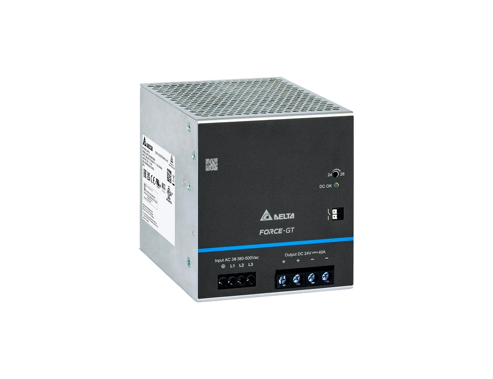

Features
- Wide Universal Input: 320...575Vac or 450...800Vdc
- Broad operating temperature range of -40°C to +70°C with derating
- Integrated constant current mode, enabling reliable performance in both load supply and charging applications
- Conformal-coated PCB assemblies protect against dust, moisture, and pollutants common in industrial settings
- Built-in DC OK relay and LED indicator provide clear status feedback for system monitoring and diagnostics
- Comparable in performance to leading European and Japanese brands, offering cost-effective alternatives
Specifications
| INPUT RATINGS/CHARACTERISTICS | |||
|---|---|---|---|
| Model Number | DRF-24V960W3GBA |
DRF-48V960W3GBA |
|
| Nominal Input Voltage | 3 x 380...500 Vac | ||
| Input Voltage Range | 3 x 320...575 Vac (3-Phase) or 2 x 340...575 Vac (2-Phase)*¹ | ||
| Nominal Input Frequency | 50...60 Hz | ||
| Input Frequency Range | 47...63 Hz | ||
| DC Input Voltage Range*² | 450...800 Vdc | ||
| Input Current | < 1.65 A @ 3 x 400 Vac, < 1.35 A @ 3 x 500 Vac | ||
| Efficiency at 100% Load | 94.5% typ. @ 3 x 400 Vac & 3 x 500 Vac | 96.0% typ. @ 3 x 400 Vac & 3 x 500 Vac | |
| Average Efficiency (25%, 50%, 75%, 100%) |
94.0% typ. @ 3 x 400 Vac & 3 x 500 Vac |
94.5% typ. @ 3 x 400 Vac & 3 x 500 Vac | |
| Max. Power Dissipation | 0% load | < 7.0 W @ 3 x 400 Vac & 3 x 500 Vac | < 7.5 W @ 3 x 400 Vac & 3 x 500 Vac |
| 100% load | < 55.0 W @ 3 x 400 Vac & 3 x 500 Vac | ||
| Max Inrush Current (Cold Start) | 35 A typ. @ 3 x 400 Vac & 3 x 500 Vac | ||
| Power Factor at 100% Load | > 0.90 @ 3 x 400 Vac & 3 x 500 Vac | ||
| Leakage Current | < 3.5 mA @ 3 x 500 Vac | ||
| *1 For 2-Phase input, see power de-rating on page 3. *2 Power supply can operate at DC input. |
|||
| OUTPUT RATINGS/CHARACTERISTICS*³ | ||
|---|---|---|
| Model Number | DRF-24V960W3GBA | DRF-48V960W3GBA |
| Nominal Output Voltage | 24 Vdc | 48 Vdc |
| Factory Set Point Tolerance | 24 Vdc ± 2% | 48 Vdc ± 1% |
| Output Voltage Adjustment Range | 24...28Vdc | 48-56 Vdc |
| Output Current | 0-40.0 A | 0-20.0 A |
| Output Power | 960W max | |
| Line Regulation | < 40 mV (@ 3 x 320-575 Vac input, 100% load) |
< 80 mV (@ 3 x 320-575 Vac input, 100% load) |
| Load Regulation | < 250 mV (@ 3 x 320-575 Vac input, 0-100% load) |
< 280 mV (@ 3 x 320-575 Vac input, 0-100% load) |
| PARD*⁴ (20MHz) | < 200 mVpp | |
| Rise Time | 85 ms typ. @ nominal input (100% load) | |
| Start-up Time | 2,000 ms typ. @ nominal input (100% load) | |
| Hold-up Time | 20 ms typ. @ 3 x 400 Vac & 500 Vac (100% load) | |
| Dynamic Response (Overshoot & Undershoot O/P Voltage) | ± 5% @ 3 x 320-575 Vac input, 5-100% load (Slew Rate: 0.1 A/μs, 50% duty cycle @ 5 Hz to 1 kHz) | ± 10% @ 3 x 320-575 Vac input, 10-100% load (Slew Rate: 0.1 A/μs, 50% duty cycle @ 5 Hz to 1 kHz) |
| Start-up with Capacitive Loads | 20,000 μF Max | |
| DC OK Relay Contact | Rated: 30 V at 1 A, resistive load. Refer to the details in the Function section at DC OK Relay Contacts and LED Indicator Characteristics on page 11. | |
| *3 For power de-rating from 55°C to 70°C, see power de-rating on page 3. *4 PARD is measured with an AC coupling mode, 5 cm wires, and in parallel to end terminal with 0.1 μF ceramic capacitor & 47 μF electrolytic capacitor. |
||
| MECHANICAL | |||
|---|---|---|---|
| Model Number | DRF-24V960W3GBA | DRF-48V960W3GBA |
|
| Case Cover / Chassis | Aluminum | ||
| Dimensions (H x W x D) | 124 x 110 x 128.7 mm (4.88 x 4.33 x 5.07 inch) | ||
| Unit Weight | 2.26 kg (4.98 lb) | ||
| Indicator | Green LED (DC OK) | ||
| Cooling System | Convection | ||
| Terminal*⁵ | Input | 4 Pins (Rated 600 V/ 30 A) | |
| Output | 4 Pins (Rated 600 V / 65 A) | ||
| DC OK | 2 Pins (Rated 300 V / 12 A) | ||
| Wire | Input | AWG 18-10 | |
| Output | AWG 12-10 | ||
| DC OK | AWG 20-16 | ||
| Mounting Rail | Standard TS35 DIN Rail in accordance with EN 60715 | ||
| Noise (1 Meter from power supply) | Sound Pressure Level (SPL) < 25 dBA | ||
| *5 The torque at the input terminal connector shall not exceed 5.4 Kgf.cm. (4.7 lbf.in). The torque at the output terminal connector shall not exceed 19.7 Kgf.cm. (17.1 lbf.in). | |||
| ENVIRONMENT | ||||
|---|---|---|---|---|
| Model Number | DRF-24V960W3GBA |
DRF-48V960W3GBA |
||
| Surrounding Air Temperature | Operating | 3-Phase -40°C to +70°C 2-Phase -40°C to +60°C |
||
| Storage | -40°C to +85°C | |||
| Power De-rating | Vertical Mounting | > 55°C de-rate power by 3.33% / °C | ||
| Horizontal Mounting | > 25°C de-rate power by 2.5% / °C | |||
| Input Voltage | 2-Phase 2 x 340-575 Vac de-rate power to 80% |
|||
| Operating Humidity | 5 to 95% RH (Non-Condensing) | |||
| Operating Altitude and Over Voltage Category | OVC III | 0 to 2,500 Meters (8,200 ft.) | According to IEC/EN 62477-1 / EN 60204-1 (clearance and creepage distances) and IEC 62103 (safety part) | |
| OVC II | 2,500 to 6,000 Meters (19,680 ft.) | |||
| 0 to 5,000 Meters (16,400 ft.) | According to IEC/EN 62368-1, IEC/EN 61010 | |||
| Shock Test | Non- Operating | IEC 60068-2-27, Half Sine Wave: 50 G for duration of 11 ms; 3 times per direction | ||
| Vibration | Operating | IEC 60068-2-6, Sine Wave: 10-500 Hz; 3G peak; 60 min per axis for all X, Y, Z directions | ||
| Pollution Degree | 2 | |||
| PROTECTIONS | ||
|---|---|---|
| Model Number | DRF-24V960W3GBA | DRF-48V960W3GBA |
| Overvoltage |
< 35 V, Hiccup Mode, Non-Latching (Auto-Recovery |
< 60 V, Hiccup Mode, Non-Latching (Auto-Recovery) |
| Overload / Overcurrent | 110 – 150% of rated load current, Auto-recovery Continuous current limit Mode*⁶ (Vo > 80 Vdc) |
110 – 150% of rated load current, Auto-recovery Continuous current limit Mode*⁶ (Vo > 80 Vdc) |
| Over Temperature | 60°C-80°C Surrounding Air Temperature @ 100% load, Non-Latching (Auto-Recovery) | |
| Short Circuit | Hiccup Mode, Non-Latching (Auto-Recovery when the fault is removed) |
|
| Internal Fust at L pin | T 4 A | |
| Degree of Protection | IP20 | |
| Protection Against Shock | Class I with PE*⁷ connection | |
| *6 Constant current limit protection for inductive and capacitive load applications *7 PE: Primary Earth |
||
| RELIABILITY DATA | ||
|---|---|---|
| MTBF | Telcordia SR-332 |
> 500,000 hrs I/P: 3 x 400 Vac & 3 x 500 Vac, O/P: 100% load, Ta: 25°C |
| Expected Cap Life Time | 10 Years | I/P: 3 x 400 Vac & 3 x 500 Vac, O/P: 50% load, Ta: 40°C |
| SAFETY STANDARDS/DIRECTIVES | ||||
|---|---|---|---|---|
| Model Number | DRF-24V960W3GBA | DRF-48V960W3GBA | ||
| Electrical Equipment of Machines | EN/BS EN 60204-1 (over voltage category III) | |||
| Electrical Equipment for Use in Electrical Power Installations | IEC/EN/BS EN 62477-1 / IEC 62103 | |||
| Safety Entry Low Voltage | SELV (IEC 60950-1) | |||
| Electrical Safety | SIQ Bauart | IEC 62368-1, IEC 60950-1, IEC 61010-1/-2-201 | ||
| UL/cUL recognized | EN/BS EN 62368-1, EN/BS EN 61010-1/-2-201 | |||
| CB scheme | UL 62368-1, UL 61010-1/-2-201 | |||
| UKCA | BS EN 62368-1, BS EN 61010-1, BS EN 61010-2-201 | |||
| EAC | TP TC 004/2011 | |||
| BIS | IS 13252 (Part 1) | |||
| Electrical Equipment for Measurement, Control, and Laboratory Use | UL/cUL listed | UL 61010-1, UL 61010-2-201 (File No. E315355) | ||
| CE | In conformance with EMC Directive 2014/30/EU and Low Voltage Directive 2014/35/EU | |||
| UKCA | In conformance with Electrical Equipment (Safety) Regulations 2016 No. 1011 and The Electromagnetic Compatibility Regulations 2016 No. 1091 | |||
| Galvanic Isolation | Input to Output | 4.0 kVac | 4.0 kVac* | |
| Input to Ground | 2.0 kVac | |||
| Output to Ground | 1.5 kVac | 1.5 kVac* | ||
| DC OK relay contact to Output | 0.5 kVac | |||
| DC OK relay contact to Ground | 1.5 kVac | |||
| *Recommend to connect all secondary pins together (connect the output pins and DC OK pins together). | ||||
| EMC*⁸ | |||||
|---|---|---|---|---|---|
| Model Number | DRF-24V960W3GBA | DRF-48V960W3GBA | |||
| Emissions (CE & RE) | Generic Standards: EN/BS EN 61000-6-3, CISPR 32, EN/BS EN 55032, KS C 9832, FCC Title 47: Class B | ||||
| Component Power Supply for General Use |
EN/BS EN 61204-3 | ||||
| Immunity | EN/BS EN 55035, KS C 9835, EN/BS EN 61000-6-2 Compliance to EN 61000-6-1 |
||||
| Electrostatic Discharge | IEC 61000-4-2 |
Level 4 Criteria A¹⁾ Air Discharge: 15 kV Contact Discharge: 8 kV |
|||
| Radiated Field | IEC 61000-4-3 |
Level 3 Criteria A¹⁾ 1.4 GHz – 2 GHz, 10 V/M, 80% Modulation (1 kHz) 2 GHz – 6 GHz, 10 V/M, 80% Modulation (1 kHz) |
|||
| Electrical Fast Transient / Burst | IEC 61000-4-4 |
Level 4 Criteria A¹⁾ 4 kV |
|||
| Surge | IEC 61000-4-5 |
Level 4 Criteria A¹⁾ |
|||
| Conducted | IEC 61000-4-6 | Level 3 Criteria A¹⁾ 150 kHz – 80 MHz, 10 Vrms |
|||
| Power Frequency Magnetic Fields | IEC 61000-4-8 | Level 4 Criteria A¹⁾ 30 A/m |
|||
| Voltage Dips and Interruptions | IEC 61000-4-11 | 0% of 3 x 380 Vac 0% of 3 x 480 Vac |
0Vac, 20ms 0Vac, 20ms |
Criteria A¹⁾ Criteria A¹⁾ |
|
| 40% of 2 x 380 Vac 40% of 2 x 480 Vac 70% of 2 x 380 Vac 70% of 2 x 480 Vac 0% |
152 Vac, 200 ms 192 Vac, 200 ms 266 Vac, 500 ms 336 Vac, 500 ms 0 Vac, 5,000 ms |
Criteria A¹⁾ Criteria A¹⁾ Criteria A¹⁾ Criteria A¹⁾ Criteria B²⁾ |
|||
| Low Energy Pulse Test (Ring Wave) |
IEC 61000-4-12 | Level 3 Criteria A¹⁾ Common Mode³⁾: 2 kV Differential Mode⁴⁾: 1 kV |
|||
| Harmonic Current Emission | IEC/EN/BS EN 61000-3-2, Class A | ||||
| Voltage Fluctuation and Flicker | IEC/EN/BS EN 61000-3-3 | ||||
| Voltage Sag Immunity SEMI F47 – 0706 | 80% of 380 Vac 70% of 380 Vac 50% of 380 Vac |
304 Vac, 1,000 ms 266 Vac, 500 ms 190 Vac, 200 ms |
Criteria A¹⁾ Criteria A¹⁾ Criteria A¹⁾ |
||
| 1) Criteria A: Normal performance within the specification limits 2) Criteria B: Temporary degradation or loss of function which is self-recoverable 3) Asymmetrical: Common mode (Line to earth) 4) Symmetrical: Differential mode (Line to line) *8 Power supply is considered a component in the end-user’s system. Please contact our local sales to get more information about the power supply EMC test setup. |
|||||
Selection Table
| MODEL NUMBER | INPUT VOLTAGE RANGE | RATED OUTPUT VOLTAGE | RATED OUTPUT CURRENT |
|---|---|---|---|
| DRF-24V960W3GBA |
3 x 320-575 Vac (3-Phase) or |
24Vdc | 40A |
| DRF-48V960W3GBA | 48Vdc | 20A |
Technical Drawings

Warranty & Returns
Warranty periods vary by product. Please refer to the Powerbox Warranty Policy for the applicable coverage period against manufacturing defects from date of purchase. For returns and RMA requests, please visit our RMA support page or contact our support team directly.
Related Products

- 120W DIN rail supply in 12V, 24V, and 48Vdc models
- Universal input 90–264Vac or 127–375Vdc operation
- DC OK relay with LED indicator for status monitoring

- 240W DIN rail supply in 24Vdc model
- Universal input 320–575Vac or 450–800Vdc operation
- DC OK relay with LED indicator for status monitoring

- 240W DIN rail supply in 12V, 24V, and 48Vdc models
- Universal input 90–264Vac or 127–375Vdc operation
- DC OK relay with LED indicator for status monitoring

- 480W DIN rail supply in 24Vdc model
- Universal input 320–575Vac or 450–800Vdc operation
- DC OK relay with LED indicator for status monitoring

- 480W DIN rail supply in 24V, and 48Vdc models
- Universal input 90–264Vac or 127–375Vdc operation
- DC OK relay with LED indicator for status monitoring